Hello,
I saw several forums here around but none of them seemed to address my problem of a byte shift.
I am using the USB dongle CC2531 to acquire data from an EMG analog front end (ADS1292) through SPI interface to the dongle and from there on via UART to USB and to the PC to display my data with Labview.
I used the rf_modem example as an base code to elaborate with additional code of mine. The dongle is succesfully recognized as virtual COM port and I see my data arrays in Hterm and Labview.
Now I have implemented an Interrupt routine for the data receive UART interrupt on the 8051 uC (in the dongle). The interrupt routine enters to the loop approx 2000 times /sec (LED blinking). I programmed an array to collect the data (dataframe[ ] ) from each ADC sample in the ADS to send some more bytes at once.
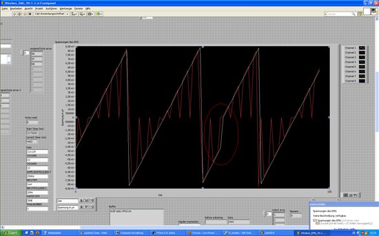
In our test signal (counter from 0-FF in 2 channels, red, white) we see a small byte shift every 9 spikes, see photo. the red channel has some introduced zeros on purpose. This problem disappears if we transport only one package of data in the dataframe at once.
The question is if anybody has any idea if this kind of byte shifting problem can come from. this deteriorates the actual data transmission.
Code:
/************************************************************************************
* @fn URX0_ISR
*
* @brief Interrupt service routine, A receive interrupt, is generated when new data is ready in the UxDBUF
* USART rec/trans. data register. ch. 17.2.1 SPI master operation.
* USART interrupt IEN bits in IEN0& IEN2 registers. INT flags in TCON & IRCON2.
* USART0 RX for SPI IEN0.URX0IE and USART0RX flag: TCON.URX0IF
* @param none
*
* @return none
*/
HAL_ISR_FUNCTION( URX0_ISR, URX0_VECTOR )
{
static signed int robISR=-3; // only done once in intialization, -3 as we want to skip the first 3 bytes (= status bits)
static int int_count=0;
static signed int packagecount = 0;
MCU_IO_OUTPUT(1, 4, 0);
MCU_IO_SET_HIGH(1,4); // (port, pin) to see the ISRs in oscillospce
// LED on CC2531 board blinking every 1000 loops of ISR
if (++int_count == 1000) {
halLedSet(2);
} else if (int_count==2000) {
halLedClear(2);
int_count = 0;
}
robISR++;
/* the data pointer now has to save the value of the SPI char and
when the data frame comes full we set dataframe ready , true*/
if (robISR == 0)
{
dataframe[robISR + packagecount * 7] = 'A';
}
else if (robISR > 0)
{ /* the robISR++ >= increases rigth after the comparison operation and not after the iteration loop.
After skipping the first 3 bytes we want to get the data bytes from two channels hence 24 bits from 2 channels = 48/8=6 bytes */
// dataframe[robISR + packagecount * 7] = U0DBUF; // to read the actual data from the buffer
switch (robISR % 3) { // test function to see if the data is inserted virually correct, checked 13.12. 2012 now we need to find where the actual bite shift occurs.
case 0:
dataframe[robISR + packagecount * 7] = 0;
case 1:
dataframe[robISR + packagecount * 7] = int_count >> 8;
case 2:
dataframe[robISR + packagecount * 7] = int_count & 0xff;
}
if(robISR == 6)
{
robISR= -3;
packagecount++;
if(packagecount == 1)
{
// dataframe[1 + (packagecount-1) * 7] = 0xFC; //corrupting the MSB of channel 1 on test purpose
dataframe[4 + (packagecount-1) * 7] = 0xFF; //corrupting the MSB of channel 2 on test purpose
Dataframeready = TRUE; // then we send the data forward in main to USB or RF buffer
packagecount = 0;
return;
}
}
}
USART0_WRITE_CHAR(0);
// in the main loop the switch the Dataframeready = FALSE ;
MCU_IO_SET_LOW(1,4);
}
/************************************************************************************
Thanks, before hand